Misreading a telehandler load chart isn’t just a mistake; it’s a risk to safety and equipment. This simple error can lead to catastrophic failures on the job site.
A telehandler load Capacity chart is a crucial safety diagram showing the machine’s maximum lifting capacity at various boom extensions and angles. Reading it correctly is the most important skill for preventing tipovers, ensuring operator safety, and protecting your investment.
I’ve been in this business for over 15 years, exporting our telehandlers from our factory here in Taian, Shandong. In that time, I’ve seen that understanding this chart is the line between a productive day and a preventable accident. It’s more than just numbers on a page; it’s the physics of safety made visual. Let’s walk through how to master it, so you can operate with confidence. This guide will break down every part of the chart, making it easy to understand and apply on any job site.
What does “Lifting Capacity” really mean for a telehandler?
You see a telehandler advertised with a “3-ton capacity.” But assuming it can lift that weight in any situation is a dangerous misunderstanding that could lead to serious trouble.
“Lifting capacity” refers to the maximum weight a telehandler can lift under specific, ideal conditions—typically with the boom fully retracted and at a low angle. This number is not constant; it decreases dramatically as the boom extends outward or upward.
Many operators misunderstand the term “rated capacity.” They think it’s a weight they can easily achieve in daily work. The truth is, the capacity listed by manufacturers is based on perfect laboratory conditions: a brand-new machine on a perfectly flat, level concrete surface, with no wind, and a perfectly centered load. Real-world job sites are rarely this perfect. Mud, worn tires, high winds, or even the temperature of the hydraulic fluid can reduce your actual safe lifting capacity.
The Idea of a “Dynamic Derating Factor”
As a manufacturer, I believe we need to teach operators to think in terms of a “Dynamic Derating Factor.” This means you start with the chart’s value and then reduce it based on your actual working conditions. It’s a mental checklist that accounts for reality.
Here’s a simple way to think about it:
| Condition | Suggested Derating Factor | Example (3000kg Rated Load) |
|---|---|---|
| Ground Surface | ||
| Hard, Level Concrete | x 1.0 | 3000 kg |
| Uneven or Soft Ground | x 0.9 | 2700 kg |
| Environmental | ||
| No Wind | x 1.0 | 3000 kg |
| Wind Speed > 10m/s | x 0.8 | 2400 kg |
| Load | ||
| Symmetrical, Centered | x 1.0 | 3000 kg |
| Off-center or Awkward | x 0.85 | 2550 kg |
If you’re on soft ground with high wind, your actual safe capacity isn’t 3000 kg anymore. It might be closer to 3000 x 0.9 x 0.8 = 2160 kg. This mindset shift is the key to true operational safety.
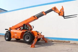
How do telehandler dimensions and sizes affect the load chart?
Telehandlers come in countless sizes, from compact 3-ton models to massive 6-ton machines. Choosing the wrong size for your job isn’t just inefficient; it’s a safety and financial risk.
The key dimensions—maximum lift height, maximum forward reach, and overall machine size—directly define the machine’s work envelope. These specifications are the foundation upon which the entire load capacity chart is built, dictating its operational limits.

The physical size of a telehandler is directly linked to its stability and, therefore, its load chart. A larger, heavier machine has more counterweight to balance a load, allowing for greater capacities at reach. In our factory, we produce a range of machines, and their charts are completely different.
Maximum Lift Height
This is how high the machine can place a load, measured from the ground to the bottom of the forks. Our models range from 7 meters up to 18 meters. A higher lift height is great, but remember, capacity drops as you go up.
Maximum Forward Reach
This is how far the machine can extend the boom horizontally from its front wheels. This is often the most critical dimension. The further you reach, the less you can carry. It’s simple physics, like holding a heavy bag close to your body versus at arm’s length.
The Link to Your Load Chart
These dimensions create a “work envelope,” which is the area the telehandler can safely operate within. A 3-ton, 7-meter telehandler is nimble and great for tight spaces, but its load chart will show much lower capacities at full extension compared to a 6-ton, 18-meter machine designed for large construction sites. When you look at a load chart, you are looking at a two-dimensional map of that machine’s specific work envelope.
How do you read and interpret a load chart correctly?
That grid of lines and numbers on the load chart can look intimidating. But guessing what it means or ignoring it altogether can lead to a tip-over accident in seconds.
To read a load chart, find your required forward reach on the horizontal axis and the lift height on the vertical axis. The point where they intersect, or the first line you cross above it, shows the maximum safe load for that exact boom position.
From my experience, accidents rarely happen because operators can’t read the numbers. They happen because the dynamic, real-world environment isn’t reflected in a static chart. Let’s break down how to read it and then how to think beyond it.
Finding the Key Data
Every load chart is based on three pieces of information:
- Rated Capacity: The number on the chart. This includes a safety factor, but it’s based on ideal conditions.
- Actual Load: This is the weight of the material plus the weight of the attachment (forks, bucket, jib).
- Machine State: Are you on tires or have you deployed stabilizers? The chart will have different capacities for each. Using stabilizers dramatically increases stability and capacity.
The Chart is Static, Your Job Isn’t
The chart assumes a perfect world. Your job site is not a perfect world. Factors like a slight slope on the ground, a gust of wind, a load that shifts, or even the jolt from suddenly releasing a load can create forces that the chart doesn’t account for. This is where operator intelligence is critical. As a personal rule of thumb, I always recommend treating the chart’s limit as a boundary you should never reach.
My independent opinion: Your true safety margin should be 15-20% below the chart’s value. This is especially true when your boom is extended beyond 70% of its maximum reach. Think of the chart as the absolute theoretical limit, not a daily work target.
Does a higher telehandler lift mean more capacity?
It’s a common and intuitive thought: lifting something straight up should be easy, right? Believing this is a fundamental misunderstanding of physics and one of the most dangerous assumptions an operator can make.
Absolutely not. Higher lift height and further reach both decrease lifting capacity. The capacity drops sharply as the load moves further away from the machine’s front wheels, which act as the pivot point for tipping.

The core principle here is “load moment,” which is simply Weight x Distance. The telehandler is a lever. Its front axle is the fulcrum (or pivot point). The machine’s body and engine act as a counterweight on one side, and your load on the boom is the weight on the other. As you extend the boom forward or upward, the distance from the fulcrum increases. This multiplies the force trying to tip the machine over, even if the weight of the load itself hasn’t changed. That’s why capacity must decrease to maintain balance.
Training for Intuition, Not Just Memory
Many training programs focus on memorizing charts: “At X meters reach and Y degrees angle, you can lift Z kilograms.” This is flawed because operators will inevitably face situations that fall between the lines on the chart. They guess, and that’s when it gets dangerous.
I believe the best safety tool isn’t the paper chart; it’s the operator’s trained intuition for physics. They need to feel the principles of center of gravity and lever arms. The future of safety, in my opinion, isn’t just a better chart. It’s technology in the cab that shows the operator a real-time display of the current load moment and the percentage of maximum capacity they are using. This provides immediate, clear feedback that a simple chart cannot.
What must you know before even looking at a load chart?
You’ve found the load chart in the cab, ready to check your lift. But if you start with the wrong information, the chart will give you a dangerously wrong answer.
Before using the load chart, you absolutely must determine three criteria: the total weight of your load, the final height it needs to reach, and the horizontal distance (forward reach) required to place it.
Getting these initial inputs right is non-negotiable. But there’s one area where I see mistakes happen over and over again: accounting for the attachments.
The Attachment Blind Spot
The standard load chart provided with a telehandler is almost always calculated for use with a standard set of forks. But on a real job site, you’re constantly swapping out attachments: from forks to a bucket, to a lifting jib, or even a personnel basket. Each of these has its own weight and, more importantly, its own center of gravity. A heavy bucket, for example, not only reduces your net capacity because of its own weight but also pushes the load’s center of gravity further forward, drastically changing the safety curve.
A Smarter Solution is Needed
Relying on the operator to remember to “subtract the weight of the bucket” is simply not enough. It’s an incomplete and risky calculation. This is the biggest blind spot in telehandler safety today.
My personal view is that the industry must move towards a better solution. Every telehandler should be equipped with a programmable attachment recognition system. When the operator connects a bucket, the machine should automatically identify it and switch to the correct load chart for that specific attachment. Our CE-certified machines are built for precision, and this is the kind of technology we need to integrate to make that precision translate into foolproof safety.
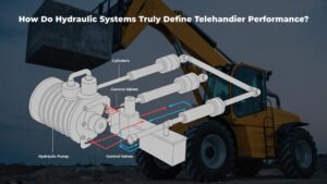
Why does the Load Moment Indicator start beeping?
You’re lifting a load, and suddenly a loud alarm starts beeping from the dashboard. Your first instinct might be to ignore it to finish the job, but that could be a fatal mistake.
The Load Moment Indicator (LMI) is a safety system that acts as an electronic watchdog. It beeps to warn you that you are approaching or have exceeded the telehandler’s safe load capacity for its current boom configuration, signaling an immediate risk of tipping over.

This system is your most important safety feature. It’s the digital brain that is constantly reading the load chart for you.
How the LMI Works
Sensors on the boom measure its angle and extension, while pressure sensors in the lift cylinder measure the force being exerted. The machine’s computer continuously calculates the load moment (Weight x Distance) in real-time. It compares this live data against the safe limits programmed into it from the manufacturer’s load chart. When you get close to the “red line” on the chart, the alarm sounds. If you continue, many modern systems will lock out the controls that make the situation worse, such as booming out or lowering the boom.
What to Do When it Activates
When the LMI alarm sounds, you must stop immediately and reverse the last action you took. If you were extending the boom, retract it. If you were lowering the boom, raise it. The goal is to bring the load closer to the machine, reducing the load moment and returning to a stable condition. Never, ever disable or ignore the LMI. It’s telling you that physics is about to win, and you will lose. Our machines, which we export globally, are equipped with reliable LMI systems because we know they are not just a feature; they are a lifeline.
Conclusion
A load chart is your most vital safety guide, but it’s only the starting point. True safety comes from understanding the real-world factors that the chart can’t show.
Follow us on :YouTube.